


Manual Floating Ball Valve
Introduction: The Workhorse of Modern Piping Systems
In the vast and intricate world of industrial fluid control, few components are as ubiquitous and critical as the Ball Valve. Among them, the manual floating ball valve stands out as a fundamental and highly reliable solution for on/off service. Since its widespread adoption in the 1950s, this valve type has evolved into a major category, prized for its simplicity, effectiveness, and versatility. Operating via a simple quarter-turn of a handle or handwheel, it provides a clear visual indication of its state—open or closed. This comprehensive guide delves deep into the manual floating ball valve, exploring its inner workings, materials, advantages, applications, and key selection criteria to help you understand why it remains a preferred choice for engineers across countless industries.
Chapter 1: Understanding the Fundamental Design and Operating Principle
1.1 What is a Manual Floating Ball Valve?
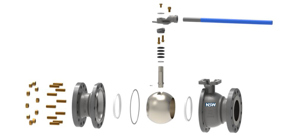
A manual Floating Ball Valve is a type of quarter-turn valve that uses a hollow, perforated, and pivoting ball to control the flow of fluids through it. The "floating" design is a key differentiator. In this configuration, the ball is not rigidly fixed to the stem. Instead, it is free to float slightly between two flexible seat rings.
1.2 The "Floating" Mechanism: A Closer Look
The magic of its sealing capability lies in this floating action. Here's a step-by-step breakdown of the mechanism:
-
In the Open Position: When the handwheel or lever is turned to open the valve, the bore (hole) of the ball aligns perfectly with the valve's inlet and outlet, creating a straight, unobstructed flow path that minimizes pressure drop.
-
Initiating Closure: As the operator begins to close the valve (typically a 90-degree turn), the stem rotates the ball so that the bore becomes perpendicular to the flow direction.
-
The Sealing Action: In the final stages of closure, the downstream seat ring plays a critical role. The pressure of the medium itself pushes the ball slightly downstream against the seat ring. This mechanical pressure, combined with the inherent elasticity of the seat material (like PTFE), creates a tight, bubble-tight seal. The higher the system pressure, the greater the force pushing the ball against the seat, thereby enhancing the seal. This is known as a "pressure-assisted" seal.
1.3 Valve Stem Design: Reliable and Leak-Free
The stem of a floating ball valve is designed for reliability. It features a precision-machined section that fits into a slot in the ball. Crucially, this stem is designed to only rotate and does not move up and down. This design eliminates axial movement that could rapidly wear out the stem packing. Furthermore, a "reverse seal" design is often incorporated at the bottom of the stem, where increasing medium pressure further compresses the seal, making stem leaks highly unlikely.
Chapter 2: Key Components and Material Selection
The performance and longevity of a manual floating ball valve are directly determined by the materials used in its construction.
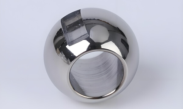
2.1 The Ball: The Heart of the Valve
-
Materials: Balls are typically made from robust materials like AISI 304 or 316 stainless steel for corrosion resistance. For less demanding applications, chrome-plated brass or carbon steel may be used.
-
Surface Finish: The ball is often chrome-plated or hard-coated to provide a smooth, durable, and low-friction surface, which is essential for long seat life.
2.2 The Seats: The Key to a Bubble-Tight Seal
The seat rings are arguably the most critical components for sealing. Modern valves use a variety of advanced polymers:
-
PTFE (Polytetrafluoroethylene): The gold standard for most applications. It offers outstanding chemical resistance, a very low coefficient of friction, and can achieve a bubble-tight seal. Variants like Reinforced PTFE (RPTFE) offer improved mechanical strength and creep resistance.
-
Nylon & DEVLON: These materials offer excellent abrasion resistance and mechanical strength, making them suitable for applications involving slurries or small solid particles.
-
PEEK (Polyether Ether Ketone): A high-performance engineering plastic capable of withstanding extreme temperatures and highly aggressive chemicals. It is used in the most demanding applications.
2.3 The Stem: Transmitting the Torque
Stems are typically made from stainless steel (e.g., 17-4PH) for its combination of strength and corrosion resistance. A proper surface finish is crucial to prevent wear on the stem seals.
2.4 The Body: The Structural Framework
Body materials are selected based on the pressure, temperature, and corrosiveness of the medium.
-
Common Materials: Carbon Steel (WCB), Stainless Steel (CF8/304, CF8M/316), Brass, and Duplex Stainless Steels for high-chloride environments.
-
End Connections: Valves come with threaded (NPT, BSP), flanged (ANSI, DIN), or socket weld ends to suit different piping system requirements.
Chapter 3: Advantages and Limitations of the Floating Ball Design
3.1 Advantages: Why Choose a Floating Ball Valve?
-
Excellent Seal: Provides reliable, bubble-tight shut-off, which is critical for safety and process integrity.
-
Compact and Simple Design: Its straightforward design makes it lightweight, cost-effective, and easy to install and maintain.
-
Quick Operation: A simple 90-degree turn allows for rapid opening and closing.
-
Low Torque and Easy Operation: The self-lubricating properties of PTFE seats ensure smooth operation with minimal manual effort.
-
Multi-Port Capabilities: While two-piece valves are common, three-piece designs and three-way configurations (L-port, T-port) offer flexibility for diverting or mixing flows.
-
Minimal Maintenance: With no complex internal mechanisms and robust stem sealing, these valves require very little upkeep.
-
Full Bore Option: Provides a flow path with no restriction, resulting in a very low pressure drop, ideal for viscous fluids or pigging operations.
3.2 Limitations: When to Consider Alternatives
-
Pressure and Size Constraints: The floating design means the ball is suspended by the seats. In very high-pressure or large-diameter applications (e.g., above 16" Class 150), the forces on the seats can become excessive, leading to high operating torque and potential seat damage. In these cases, a trunnion-mounted ball valve is preferred.
-
Limited to On/Off Service: Standard floating ball valves are not designed for precise flow control or throttling. Using them in a partially open state for extended periods can cause cavitation, erosion, and premature seat wear. For control applications, a V-notch ball valve is the correct choice.
Chapter 4: Industrial Applications Across Sectors
The manual floating ball valve's versatility makes it suitable for a wide array of industries:
-
Oil & Gas: Used in upstream and midstream applications for crude oil, fuel gas, and water lines where tight shut-off is required.
-
Chemical & Petrochemical: Handles a wide range of acids, alkalis, and solvents, thanks to the chemical resistance of PTFE and stainless steel construction.
-
Water & Wastewater: Ideal for potable water distribution, treatment plants, and effluent handling due to their corrosion resistance and full-bore capability.
-
Power Generation: Found in cooling water systems, feedwater lines, and auxiliary services in both conventional and nuclear plants.
-
Pharmaceutical & Food & Beverage: Sanitary designs with polished internals and compliance with FDA/USP Class VI standards are used for hygienic fluid transfer.
-
HVAC: Used in heating and cooling water circuits for isolation purposes.
Chapter 5: Selection Guide: How to Choose the Right Valve
Selecting the correct manual floating ball valve is crucial for system performance and safety. Consider these factors:
-
Medium: What fluid is being controlled? Consider its chemical composition, temperature, and whether it contains abrasives or solids.
-
Pressure & Temperature Rating: Ensure the valve's pressure class (e.g., ANSI 150, 300) and temperature range are suitable for your system's operating conditions.
-
Material Compatibility: Match the body, ball, seat, and stem materials to the medium to prevent corrosion and degradation.
-
End Connection: Choose threads (NPT/BSP), flanges, or socket weld based on your piping system.
-
Bore Type:
-
Full Port (Full Bore): The bore diameter matches the pipe ID. Use for applications with minimal pressure drop, viscous fluids, or where pipeline pigging is required.
-
Reduced Port (Reduced Bore): The bore is one size smaller than the pipe ID. This is a cost-effective and compact option for general purpose applications where a slight pressure drop is acceptable.
-
-
Fire-Safe Design: For applications with fire risk, specify valves that comply with API 607/API 6FA standards, which ensure the valve can maintain a seal even if the soft seats are destroyed by fire.
-
Antistatic Design: To prevent the buildup of static electricity from the flow of hydrocarbons, valves can be equipped with a spring mechanism that ensures electrical continuity between the ball, stem, and body.
Chapter 6: Installation, Operation, and Maintenance Best Practices
-
Installation: While these valves are generally bidirectional, it is recommended to install them with the stem horizontal. Installing them with the stem vertical, especially in larger sizes, can put uneven load on the stem and seats. Ensure the pipeline is clean before installation to prevent damage from debris.
-
Operation: Operate the valve smoothly and do not use excessive force. The valve should be either fully open or fully closed. Avoid using it as a control valve.
-
Maintenance: The three-piece body design is a significant advantage here. It allows for easy removal from the pipeline for inspection or seat replacement without disturbing the pipework, drastically reducing maintenance downtime.
Conclusion
The manual floating ball valve is a masterpiece of pragmatic engineering. Its simple yet highly effective floating ball principle, combined with advanced material science, has secured its place as a cornerstone of fluid control systems worldwide. By understanding its design nuances, advantages, limitations, and proper application guidelines, engineers and technicians can make informed decisions that ensure system reliability, safety, and efficiency for years to come. Whether in a chemical plant, a water treatment facility, or an offshore platform, this versatile valve continues to prove its worth as a dependable and efficient solution for critical isolation tasks.
The Complete Guide to Manual Floating Ball Valves: Design, Applications, and Selection
Introduction: The Workhorse of Modern Piping Systems
In the vast and intricate world of industrial fluid control, few components are as ubiquitous and critical as the ball valve. Among them, the manual floating ball valve stands out as a fundamental and highly reliable solution for on/off service. Since its widespread adoption in the 1950s, this valve type has evolved into a major category, prized for its simplicity, effectiveness, and versatility. Operating via a simple quarter-turn of a handle or handwheel, it provides a clear visual indication of its state—open or closed. This comprehensive guide delves deep into the manual floating ball valve, exploring its inner workings, materials, advantages, applications, and key selection criteria to help you understand why it remains a preferred choice for engineers across countless industries.
Chapter 1: Understanding the Fundamental Design and Operating Principle
1.1 What is a Manual Floating Ball Valve?
A manual floating ball valve is a type of quarter-turn valve that uses a hollow, perforated, and pivoting ball to control the flow of fluids through it. The "floating" design is a key differentiator. In this configuration, the ball is not rigidly fixed to the stem. Instead, it is free to float slightly between two flexible seat rings.
1.2 The "Floating" Mechanism: A Closer Look
The magic of its sealing capability lies in this floating action. Here's a step-by-step breakdown of the mechanism:
-
In the Open Position: When the handwheel or lever is turned to open the valve, the bore (hole) of the ball aligns perfectly with the valve's inlet and outlet, creating a straight, unobstructed flow path that minimizes pressure drop.
-
Initiating Closure: As the operator begins to close the valve (typically a 90-degree turn), the stem rotates the ball so that the bore becomes perpendicular to the flow direction.
-
The Sealing Action: In the final stages of closure, the downstream seat ring plays a critical role. The pressure of the medium itself pushes the ball slightly downstream against the seat ring. This mechanical pressure, combined with the inherent elasticity of the seat material (like PTFE), creates a tight, bubble-tight seal. The higher the system pressure, the greater the force pushing the ball against the seat, thereby enhancing the seal. This is known as a "pressure-assisted" seal.
1.3 Valve Stem Design: Reliable and Leak-Free
The stem of a floating ball valve is designed for reliability. It features a precision-machined section that fits into a slot in the ball. Crucially, this stem is designed to only rotate and does not move up and down. This design eliminates axial movement that could rapidly wear out the stem packing. Furthermore, a "reverse seal" design is often incorporated at the bottom of the stem, where increasing medium pressure further compresses the seal, making stem leaks highly unlikely.
Chapter 2: Key Components and Material Selection
The performance and longevity of a manual floating ball valve are directly determined by the materials used in its construction.
2.1 The Ball: The Heart of the Valve
-
Materials: Balls are typically made from robust materials like AISI 304 or 316 stainless steel for corrosion resistance. For less demanding applications, chrome-plated brass or carbon steel may be used.
-
Surface Finish: The ball is often chrome-plated or hard-coated to provide a smooth, durable, and low-friction surface, which is essential for long seat life.
2.2 The Seats: The Key to a Bubble-Tight Seal
The seat rings are arguably the most critical components for sealing. Modern valves use a variety of advanced polymers:
-
PTFE (Polytetrafluoroethylene): The gold standard for most applications. It offers outstanding chemical resistance, a very low coefficient of friction, and can achieve a bubble-tight seal. Variants like Reinforced PTFE (RPTFE) offer improved mechanical strength and creep resistance.
-
Nylon & DEVLON: These materials offer excellent abrasion resistance and mechanical strength, making them suitable for applications involving slurries or small solid particles.
-
PEEK (Polyether Ether Ketone): A high-performance engineering plastic capable of withstanding extreme temperatures and highly aggressive chemicals. It is used in the most demanding applications.
2.3 The Stem: Transmitting the Torque
Stems are typically made from stainless steel (e.g., 17-4PH) for its combination of strength and corrosion resistance. A proper surface finish is crucial to prevent wear on the stem seals.
2.4 The Body: The Structural Framework
Body materials are selected based on the pressure, temperature, and corrosiveness of the medium.
-
Common Materials: Carbon Steel (WCB), Stainless Steel (CF8/304, CF8M/316), Brass, and Duplex Stainless Steels for high-chloride environments.
-
End Connections: Valves come with threaded (NPT, BSP), flanged (ANSI, DIN), or socket weld ends to suit different piping system requirements.
Chapter 3: Advantages and Limitations of the Floating Ball Design
3.1 Advantages: Why Choose a Floating Ball Valve?
-
Excellent Seal: Provides reliable, bubble-tight shut-off, which is critical for safety and process integrity.
-
Compact and Simple Design: Its straightforward design makes it lightweight, cost-effective, and easy to install and maintain.
-
Quick Operation: A simple 90-degree turn allows for rapid opening and closing.
-
Low Torque and Easy Operation: The self-lubricating properties of PTFE seats ensure smooth operation with minimal manual effort.
-
Multi-Port Capabilities: While two-piece valves are common, three-piece designs and three-way configurations (L-port, T-port) offer flexibility for diverting or mixing flows.
-
Minimal Maintenance: With no complex internal mechanisms and robust stem sealing, these valves require very little upkeep.
-
Full Bore Option: Provides a flow path with no restriction, resulting in a very low pressure drop, ideal for viscous fluids or pigging operations.
3.2 Limitations: When to Consider Alternatives
-
Pressure and Size Constraints: The floating design means the ball is suspended by the seats. In very high-pressure or large-diameter applications (e.g., above 16" Class 150), the forces on the seats can become excessive, leading to high operating torque and potential seat damage. In these cases, a trunnion-mounted ball valve is preferred.
-
Limited to On/Off Service: Standard floating ball valves are not designed for precise flow control or throttling. Using them in a partially open state for extended periods can cause cavitation, erosion, and premature seat wear. For control applications, a V-notch ball valve is the correct choice.
Chapter 4: Industrial Applications Across Sectors
The manual floating ball valve's versatility makes it suitable for a wide array of industries:
-
Oil & Gas: Used in upstream and midstream applications for crude oil, fuel gas, and water lines where tight shut-off is required.
-
Chemical & Petrochemical: Handles a wide range of acids, alkalis, and solvents, thanks to the chemical resistance of PTFE and stainless steel construction.
-
Water & Wastewater: Ideal for potable water distribution, treatment plants, and effluent handling due to their corrosion resistance and full-bore capability.
-
Power Generation: Found in cooling water systems, feedwater lines, and auxiliary services in both conventional and nuclear plants.
-
Pharmaceutical & Food & Beverage: Sanitary designs with polished internals and compliance with FDA/USP Class VI standards are used for hygienic fluid transfer.
-
HVAC: Used in heating and cooling water circuits for isolation purposes.
Chapter 5: Selection Guide: How to Choose the Right Valve
Selecting the correct manual floating ball valve is crucial for system performance and safety. Consider these factors:
-
Medium: What fluid is being controlled? Consider its chemical composition, temperature, and whether it contains abrasives or solids.
-
Pressure & Temperature Rating: Ensure the valve's pressure class (e.g., ANSI 150, 300) and temperature range are suitable for your system's operating conditions.
-
Material Compatibility: Match the body, ball, seat, and stem materials to the medium to prevent corrosion and degradation.
-
End Connection: Choose threads (NPT/BSP), flanges, or socket weld based on your piping system.
-
Bore Type:
-
Full Port (Full Bore): The bore diameter matches the pipe ID. Use for applications with minimal pressure drop, viscous fluids, or where pipeline pigging is required.
-
Reduced Port (Reduced Bore): The bore is one size smaller than the pipe ID. This is a cost-effective and compact option for general purpose applications where a slight pressure drop is acceptable.
-
-
Fire-Safe Design: For applications with fire risk, specify valves that comply with API 607/API 6FA standards, which ensure the valve can maintain a seal even if the soft seats are destroyed by fire.
-
Antistatic Design: To prevent the buildup of static electricity from the flow of hydrocarbons, valves can be equipped with a spring mechanism that ensures electrical continuity between the ball, stem, and body.
Chapter 6: Installation, Operation, and Maintenance Best Practices
-
Installation: While these valves are generally bidirectional, it is recommended to install them with the stem horizontal. Installing them with the stem vertical, especially in larger sizes, can put uneven load on the stem and seats. Ensure the pipeline is clean before installation to prevent damage from debris.
-
Operation: Operate the valve smoothly and do not use excessive force. The valve should be either fully open or fully closed. Avoid using it as a control valve.
-
Maintenance: The three-piece body design is a significant advantage here. It allows for easy removal from the pipeline for inspection or seat replacement without disturbing the pipework, drastically reducing maintenance downtime.
Conclusion
The manual floating ball valve is a masterpiece of pragmatic engineering. Its simple yet highly effective floating ball principle, combined with advanced material science, has secured its place as a cornerstone of fluid control systems worldwide. By understanding its design nuances, advantages, limitations, and proper application guidelines, engineers and technicians can make informed decisions that ensure system reliability, safety, and efficiency for years to come. Whether in a chemical plant, a water treatment facility, or an offshore platform, this versatile valve continues to prove its worth as a dependable and efficient solution for critical isolation tasks.
Post time: Nov-20-2020