


What is a Globe Valve
In industrial piping systems, building water supply and drainage, and various fluid control scenarios, the globe valve is a widely used forced-seal shut-off valve. Its core function is to precisely control the flow and blockage of media (such as liquids, gases, steam) within a pipeline. It operates by converting the rotational motion of the stem into a vertical, linear movement of the disc—when the disc’s sealing surface tightly presses against the seat sealing surface, the flow path closes, and media flow is blocked; when the disc is lifted away from the seat, the flow path opens, allowing media to pass through, enabling flexible fluid control.

Core Components of a Globe Valve
The stable operation of a Globe Valve relies on the coordinated work of several key components, each performing a specific function to ensure the valve’s sealing performance and operational reliability.

Body
The body is the “main frame” of the globe valve, typically made from cast iron, carbon steel, stainless steel, or other corrosion-resistant, high-strength materials. It contains the internal flow channel (inlet and outlet). The body must withstand the pressure of the media inside the pipeline and provide the foundation for mounting and positioning internal parts like the seat and disc, making it the core component for overall structural strength.
Disc
The disc is the key sealing component that controls media flow, often working in conjunction with the plug in some designs. Its shape and material are selected based on media characteristics (e.g., corrosiveness, temperature, pressure). For instance, metal is common in high-pressure scenarios, while rubber or plastic may be used for low-pressure corrosive applications. The disc achieves a sealed closure by mating closely with the seat.
Seat
The seat is the sealing “reference surface” of the globe valve, fixed within the body at the media flow channel. Its surface is precision-machined to ensure tight contact with the disc’s sealing surface. Seat material requires good wear and sealing resistance, commonly including copper alloy, stainless steel, and hard alloys to combat long-term erosion from media and extend valve seal life.
Stem
The stem is the “transmission bridge” connecting the actuator to the disc, typically a threaded rod. One end is fixed to the disc, and the other connects to the actuator (e.g., handwheel, electric motor). It converts the driving force into the disc’s vertical linear movement via rotational motion. The stem must possess sufficient strength and fatigue resistance, and its surface is often chrome-plated or nitrided to reduce friction and prevent corrosion.
Actuator
The actuator is the “power source” of the globe valve, used to control the stem’s rotation for opening and closing. Based on the operation method, actuators are divided into manual and automatic types:
- Manual Actuators: Suitable for low-frequency operation and small-diameter pipelines; simple structure, lower cost.
- Automatic Actuators: Suitable for remote control, high-frequency operation, or large-diameter scenarios; can be integrated with control systems for automated regulation, improving operational efficiency. Types include pneumatic, electric, and hydraulic actuators.
How Does a Globe Valve Work?
The working principle of a globe valve is based on a “forced seal” and “linear seal” design logic, which can be broken down into two stages: opening and closing.
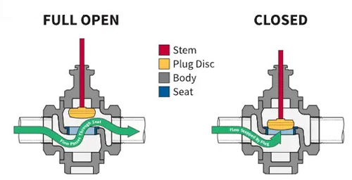
- Closing State: The stem is “screwed in,” driving the disc downward along the seat’s vertical axis until the disc’s sealing face presses tightly against the seat’s sealing face. As a forced-seal valve, the contact pressure between the disc and seat ensures sealing even under low media pressure, preventing flow.
- Opening State: To open the valve, the stem is rotated in the reverse direction (manually or via an actuator), lifting the disc away from the seat and creating a gap. Media can flow from the inlet to the outlet through this gap. By controlling the lift height of the disc, the gap size—and thus the flow rate—can be regulated (throttling function).
- Core Logic: The seal relies on “face-to-face” contact between the disc and seat, unlike the “parallel sliding” of gates in gate valves. This design offers more reliable sealing when closed, especially in scenarios requiring strict flow blockage.
Globe Valve Advantages and Disadvantages
The design characteristics of globe valves give them significant advantages in specific scenarios, but they also have limitations. Selection should be based on a comprehensive assessment of application requirements.
Advantages of Globe Valves
- Excellent Sealing Performance: As a forced-seal valve, the sealing pressure can be actively controlled, ensuring a reliable seal and preventing leakage, even in low-pressure environments.
- Strong Throttling Capability: Precise flow control is achievable by adjusting the disc lift height. This is suitable for scenarios requiring frequent flow adjustment and reduces fluid erosion on the disc and seat, extending service life.
- Compact Structure, Easy Maintenance: The overall structure is relatively simple with fewer parts, requiring less installation space. Most components (e.g., disc, seat) can be individually disassembled and replaced, resulting in lower maintenance costs.
- Wide Application Range: Suitable for various media including water, oil, steam, and gas, and capable of withstanding high temperatures and pressures (special high-temperature high-pressure models are used in steam systems).
Disadvantages of Globe Valves
- High Pressure Loss: Due to the seat design, which is parallel to the flow direction, fluid must change direction (from inlet to seat, then to outlet), causing turbulence and vortices. This results in higher pressure loss compared to gate or ball valves.
- Not Suitable for High-Viscosity or Contaminated Media: Impurities (e.g., particles, sediment) can easily get trapped between the disc and seat, damaging the seal. High-viscosity media can cause high flow resistance, making operation difficult.
- High Opening/Closing Torque: The threaded stem-disc connection and the required sealing pressure mean globe valves need higher operating torque compared to gate valves, especially in large-diameter or high-pressure applications.
Types of Globe Valves
Globe valves can be classified into various types based on material, structure, and actuation method, each suited for different applications.
Classification by Material
- Bellows Seal Globe Valve: Uses a bellows seal structure to effectively prevent media leakage along the stem. Ideal for toxic, flammable, or high-purity media (e.g., chemical, pharmaceutical industries), offering far superior sealing.
- Carbon Steel Globe Valve: The body is made of carbon steel (e.g., Q235, 20# steel), offering good strength and temperature resistance at a low cost. Suitable for general industrial pipelines (e.g., water supply, heating systems), but has poor corrosion resistance.
- Stainless Steel Globe Valve: The body is made of stainless steel (e.g., 304, 316), providing excellent corrosion and high-temperature resistance. Used for corrosive media (e.g., chemical solutions, seawater) or in food and pharmaceutical industries with high hygiene requirements.
- Aluminum Bronze Globe Valve: The body is made of aluminum bronze, offering good wear and impact resistance, along with certain corrosion resistance. Suitable for ships, offshore engineering, and other humid, high-salinity environments.
- Cryogenic Globe Valve: Made from cryogenic-resistant materials (e.g., low-temperature stainless steel) with special seal structures, these valves operate in environments from -40°C to -196°C. Used for liquefied natural gas (LNG), liquid nitrogen, and other cryogenic media pipelines.
- High-Temperature Globe Valve: The body and sealing components use high-temperature materials (e.g., chrome-molybdenum steel, high-temperature alloys), withstanding temperatures above 400°C. Used in steam boilers, high-temperature thermal oil systems, and other high-temperature media systems.
Classification by Structure
- Straight-Type Globe Valve: The most common type, with inlet and outlet in a straight line. Fluid makes only one direction change, resulting in relatively lower pressure loss. Widely used in various piping systems.
- Three-Way Globe Valve: Has three ports (typically one inlet/two outlets or two inlets/one outlet) for diverting or mixing media flows. Used in scenarios requiring flow direction switching.
- Angle-Type Globe Valve: The inlet and outlet are at a 90° angle, ideal for installation at pipe corners. This reduces the need for pipe elbows and saves space, common in compact equipment or confined spaces.
Classification by Actuation Method
- Manual Globe Valve: Operated via a handwheel or lever to rotate the stem. Simple structure, low cost, suitable for low-frequency operation and small diameters (≤DN50), like domestic water valves or small equipment lines.
- Pneumatic Globe Valve: Uses compressed air to actuate the stem via a pneumatic actuator. Fast response, suitable for automation in chemical, petroleum, and other industries requiring high-frequency operation or remote control.
- Electric Globe Valve: Uses electricity to drive the stem via an electric actuator. High control precision, can be integrated with PLC/DCS systems for smart control. Used in large pipelines, high-rise buildings, or unmanned automated systems.
Classification by Function
- Check Globe Valve: Combines the functions of a globe valve and a check valve. It can shut off flow and prevent backflow (e.g., protecting against water hammer when a pump stops). Used at pump outlets, heating systems, and other scenarios requiring backflow prevention.
How to Identify Globe Valves vs. Gate Valves & Other Valves
In practical engineering, globe valves are often confused with gate, ball, check, and butterfly valves. They can be quickly identified by comparing key characteristics.
Globe Valve vs. Gate Valve
| Aspect | Globe Valve | Gate Valve |
|---|---|---|
| Core Structure | Disc moves vertically along seat axis | Gate moves parallel to the seat |
| Sealing Method | Forced Seal (disc pressed onto seat) | Non-forced Seal (media pressure aids seal) |
| Flow Control | Can throttle flow precisely | On/Off only (throttling causes gate erosion) |
| Pressure Loss | Higher (fluid must change direction) | Lower (straight-through flow) |
| Typical Use Case | Frequent flow adjustment, low-pressure sealing | Large diameter, high flow, low pressure loss |
| Operating Torque | Higher (must overcome sealing pressure) | Lower (less resistance to gate movement) |
Globe Valve vs. Ball Valve
| Aspect | Globe Valve | Ball Valve |
|---|---|---|
| Core Structure | Disc moves up and down | Ball rotates around its axis (90° operation) |
| Switching Speed | Slower (requires multiple stem rotations) | Very Fast (quarter-turn) |
| Sealing Performance | Reliable at low pressure, wears at high pressure | Reliable across all pressures (tight seal) |
| Pressure Loss | Higher | Minimal (smooth bore) |
| Suitable Media | Clean media (prone to clogging with solids) | Clean / slightly contaminated media |
| Cost | Low to Medium (simple structure) | Medium to High (high precision required) |
Globe Valve vs. Check Valve
| Aspect | Globe Valve | Check Valve |
|---|---|---|
| Core Function | Active flow control and shut-off, throttling | Passive backflow prevention (no active control) |
| Operation Method | Manual/Automatic actuation (active control) | No actuator (relies on pressure differential) |
| Complexity | More complex (has actuator, stem) | Simple (has disc, spring, no actuator) |
| Typical Use Case | Pipelines requiring active flow control | Prevents backflow (e.g., pump discharge) |
| Installation | Must be installed with correct flow direction | Must be installed with correct flow direction |
Globe Valve vs. Butterfly Valve
| Aspect | Globe Valve | Butterfly Valve |
|---|---|---|
| Core Structure | Disc moves up and down | Disc rotates around a shaft (90° operation) |
| Space Required | Larger (needs space for stem travel) | Very Compact (good for large diameters) |
| Pressure Loss | Higher | Lower (low resistance when fully open) |
| Sealing Performance | Can leak in high-pressure (seat wear) | Good at low pressure, needs special seals for high pressure |
| Suitable Pipe Size | Small to Medium diameters (≤DN200) | Medium to Large diameters (DN50 to DN1000+) |
| Maintenance | Easier (components accessible) | Harder (often requires full disassembly) |
What is a Globe Valve Used For?
Leveraging their reliable sealing and throttling capabilities, globe valves are widely used across various industries and applications.
- Industrial Piping Systems: Used for media control in chemical, petroleum, and power industries—e.g., steam line isolation/flow regulation, chemical solution transfer control—especially where tight sealing at low pressure is critical.
- Building Water Supply & Drainage: Serves as terminal control valves in residential/commercial building water and heating pipelines (e.g., bathroom/kitchen supply lines) for manual flow adjustment or shut-off.
- Equipment Integration: Acts as inlet/outlet valves for machinery like pumps, heat exchangers, and compressors, controlling media flow to/from the equipment and protecting it (e.g., preventing backflow, regulating inlet flow).
- High-Temperature & High-Pressure Services: Special types (high-temperature, high-pressure globe valves) are used in steam boilers and thermal oil systems, utilizing their ability to withstand extreme conditions for reliable control.
- Food & Pharmaceutical Industry: Stainless steel globe valves, known for high corrosion resistance and cleanability, are used for media transfer (e.g., pharmaceuticals, pure water) where sanitary standards are required.
How to Install a Globe Valve
Proper installation is crucial for the sealing performance and service life of a globe valve. Follow these steps and precautions.
Pre-Installation Preparation
- Inspect the Valve: Confirm the valve model/specifications match pipeline requirements (pressure rating, media type, size). Check the body, disc, and seat for damage or debris; ensure sealing surfaces are intact.
- Clean the Pipeline: Remove internal impurities (rust, weld slag) to prevent them from jamming between the disc and seat after installation, which could damage the seal.
- Confirm Flow Direction: Globe valves are unidirectional. The body usually has a flow direction arrow (“IN” → “OUT”). Ensure the arrow aligns with the actual media flow; reverse installation will cause seal failure.
Installation Steps
- Positioning & Fixing: Place the valve between pipe ends, ensuring it is coaxial with the pipeline to avoid stress concentration. Secure it via flanged or threaded connections (for flanged, tighten bolts evenly to prevent body distortion).
- Sealing Treatment: For threaded valves, wrap thread seal tape or apply sealant on the threads. For flanged valves, install a compatible gasket (e.g., rubber, metal) to ensure leak-free connections.
- Actuator Installation: For automatic valves (pneumatic, electric), align and connect the actuator to the stem for smooth operation. Connect control wiring (electric) or air lines (pneumatic) and perform functional tests.
Post-Installation Inspection
- Manual Test: After installation, manually rotate the stem (or activate the actuator) to check for smooth opening/closing without sticking.
- Leak Test: Introduce media into the pipeline (low-pressure test run). Check for leaks at the valve body and connection points. If leaks are found, re-tighten bolts or replace seals.
Globe Valve Maintenance
Regular maintenance is essential to extend service life and ensure long-term, reliable operation.
Regular Inspections
- Visual Inspection: Weekly checks for body corrosion, cracks, connection leaks, and stem rust or deformation.
- Operational Check: Manually or automatically operate the valve 1-2 times monthly to prevent the stem from seizing due to inactivity, especially in humid/corrosive environments.
- Seal Inspection: Perform leak tests periodically (e.g., quarterly). For high-pressure lines, apply soapy water to sealing points; bubbles indicate leakage.
Cleaning and Lubrication
- Body Cleaning: Regularly wipe the exterior with water or a neutral cleaner to remove dust/oil and prevent corrosive substance buildup.
- Stem Lubrication: Lubricate the stem threads every six months with a suitable lubricant (e.g., graphite grease, specialized valve lubricant) to reduce thread wear and ensure smooth operation. Ensure lubricant compatibility with the media to avoid contamination.
Part Replacement & Repair
- Seal Replacement: If the disc or seat sealing surface is worn or leaking, disassemble the valve and replace the seals (disc ring, seat gasket). After replacement, re-lap the sealing surfaces for tight contact.
- Stem Repair/Replacement: If the stem is corroded or the threads are damaged, perform derusting or replace the stem to avoid operational failure.
- Actuator Maintenance: For pneumatic valves, regularly check air lines for leaks and actuator function. For electric valves, inspect control wiring and motors to prevent operational failure due to drive issues.
Long-Term Storage Maintenance
- If a globe valve is out of service long-term (e.g., over 3 months), close the isolation valves upstream and downstream, drain media from the pipeline, and apply anti-rust treatment (e.g., anti-corrosion oil) to the internal body and sealing surfaces. Inspect the valve status periodically.
![]()
Frequently Asked Questions (FAQ)
Here are answers to some of the most common questions about globe valves.
What is the P&ID symbol for a globe valve?
The standardized Piping and Instrumentation Diagram (P&ID) symbol for a globe valve is characterized by two triangles pointing towards each other, connected by a line that represents the flow path through the valve body. The symbol visually represents the globe valve’s function of creating a restrictive orifice to control flow.

Does a globe valve has Flow Directional?
Yes, Globe valves are strictly unidirectional, so it has Flow Directional. The internal design of the disc and seat is engineered for optimal sealing in one direction only. The valve body is typically marked with an arrow indicating the correct flow direction. Installing the valve against this specified flow direction will prevent it from sealing properly and can lead to rapid wear and leakage.
Can globe valves be used for high-temperature high-pressure steam systems?
Absolutely. Globe valves are an excellent choice for high-temperature and high-pressure applications, including steam systems. Their forced-seal design ensures a tight shut-off even under extreme conditions. Specialized materials like Chrom-Moly steel (WC9) and hardened trim are often used in high-performance globe valves to withstand the thermal and mechanical stresses of steam service.

Is a globe valve a shut-off valve?
Yes, a globe valve is a type of shut-off valve. The term “shut-off valve” is a functional classification for any valve designed to start or stop fluid flow. Other common shut-off valves include gate valves, ball valves, and butterfly valves. While all these can stop flow, the globe valve is often preferred when a combination of reliable sealing and flow regulation is required.
Can a globe valve be used as a control valve?
A standard globe valve can be used for rough throttling in applications where precise control is not critical. However, for accurate and repeatable flow control, a dedicated globe control valve is used. The key difference is in the disc design: control valves feature a specially engineered tapered plug or V-port disc (as opposed to a flat disc) and a specially designed cage, which allows for precise linear flow characteristics.
Post time: Jan-10-2025